To help ensure the integrity of EV isolation, the Automatic Fraction Collector (AFC) V2 has an in-built system for detecting vibrations that may compromise accurate weight measurements and subsequent volume collection. In this article, we outline essential factors to consider in order to prevent vibrations from disrupting your sample processing.
1. Check the AFC’s surroundings
If the AFC indicates abnormal vibrations have been detected (Figure 1), first ensure your AFC has been set up according to the AFC V2 user manual; on a level, stable bench away from any equipment that could cause vibrations, such as a centrifuge, plate shaker, vortex mixer, or sonication device.
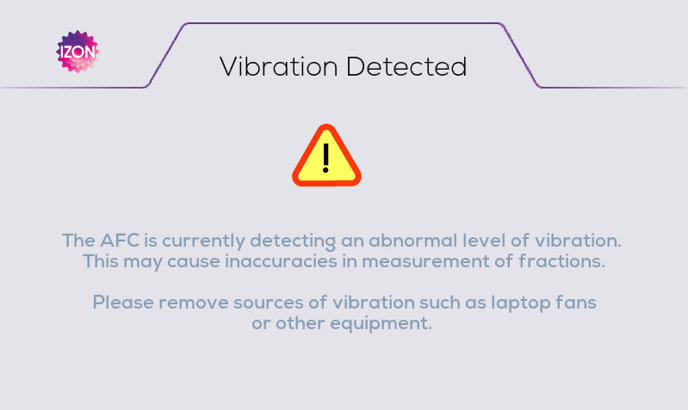 Figure 1. Error message displayed when an abnormal level of vibration is detected.
2. Ensure the nozzle set is fitted correctly
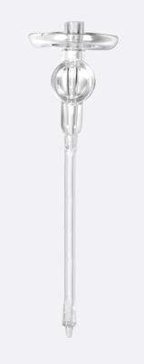
Figure 2. Nozzle set: The entirety of the silicone tubing, and the adaptor used to connect qEV columns to the tubing.
A well-fitted nozzle set (Figure 3), with silicone tubing correctly in place, allows the valve to close completely and pause the flow at the appropriate time.
Conversely, if the nozzle set is not fitted properly (and the tubing is not aligned correctly, Figure 4), the valve will not be able to close completely. Consequently, there may be an ongoing flow of fluid from the nozzle tip, albeit to a limited extent. Any resulting droplets will then hit the carousel, potentially causing the carousel to detect a vibration.
Ensuring proper fitting of the nozzle set is crucial for maintaining functionality of the AFC – and is also a useful troubleshooting step in preventing unwanted vibration detection.
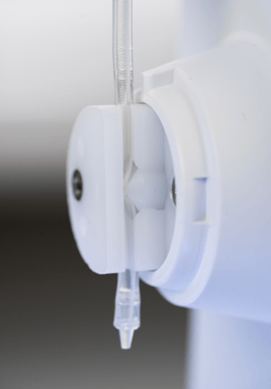
Figure 3. Correct nozzle/tube placement. Note that the valve is closed and is pinching the tubing shut.
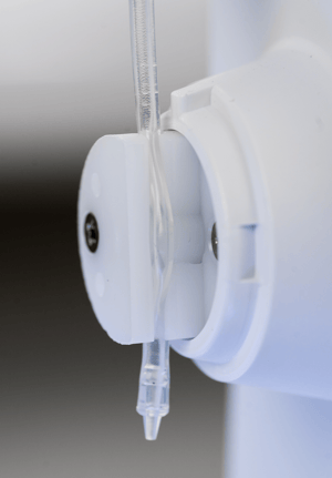
Figure 4. An incorrectly fitted nozzle set with tubing not in place. Note that the tubing is not aligned and therefore the valve will not be able to function properly.
How to fit the nozzle set correctly
Follow the instructions below and check out the following resources:
- Instructions on how to change the nozzle set (and more related photos) are also detailed in the AFC V2 user manual; see the section titled “Replacing the Nozzle”
- Watch this video for a demonstration: How to Change the Automatic Fraction Collector (AFC) V2 Nozzle“
Remove the nozzle set:
- Open the Settings menu and navigate to the fluid tab, then toggle the valve open.
- Remove the pinch valve cover by grasping it firmly and gently pulling away from the AFC tower.
- Firmly grasp the nozzle tube above and below the pinch valve housing and gently pull away (laterally) until the nozzle tube is free.
Visually inspect the nozzle set:
At this point, it is a good idea to inspect your nozzle set; look closely for cracks or any signs of aging in the tubing. Each AFC is fitted with a nozzle set and comes with 3 spare nozzle sets which can be used when deemed appropriate. AFC Nozzle Sets can also be purchased as 10-packs on the Izon Store.
Fit your nozzle set and check flow to ensure fit:
- Firmly grasp the tube either side of where it will fit into the pinch valve housing, and slot it into place. The silicone tube slides in more easily if the valve is open. You may need to stretch the tubing downwards slightly to get it into place.
- Use your fingertip and press the tube gently to help check it is in place; replace the pinch valve cover and refer to photos in the user manual to see how the set should look when the pinch valve cover is on.
To check you have successfully fitted the nozzle, run DI water (or other fluid, e.g. buffer) through the nozzle set (no column required at this stage). Ensure you have full control over fluid flow; i.e., check that dripping stops when you close the valve, and resumes when you open it.